Computer Controlled Cutting
Computer-controlled cutting is a subtractive manufacturing method in which a computer uses a digital design file to control an effector (a knife, laser, water jet, hot wire, or endmill). The laser cutter and vinyl cutter were among the machines we discussed this week.
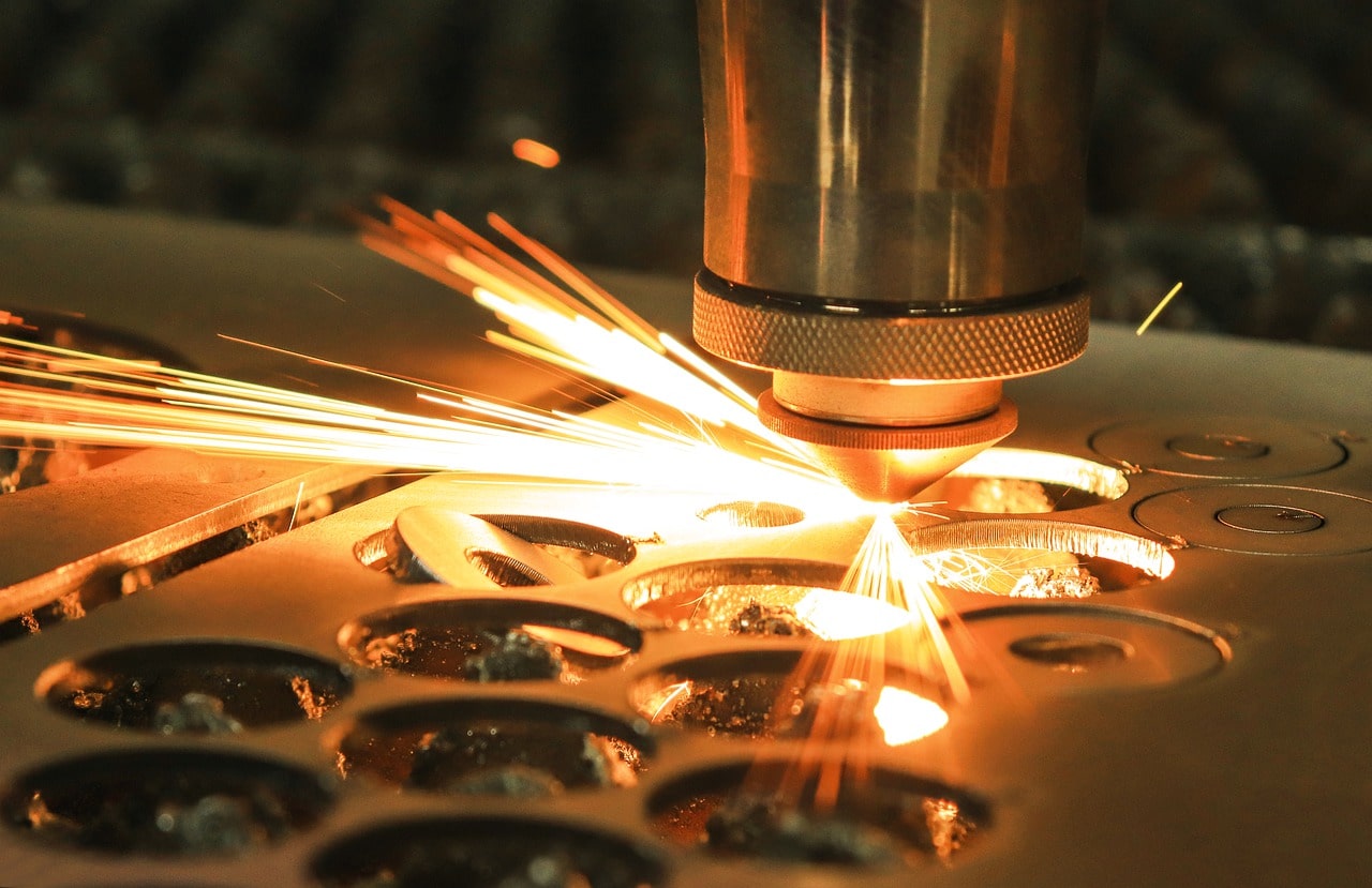
The laser cutter is an essential machine in a Fab Lab. Laser cutting allows for precision levels and edge quality that would be unable with traditional cutting methods, since the laser beam won't wear during the cutting process. Additionally, laser enables cutting complex designs at faster speeds than other cutting methods.
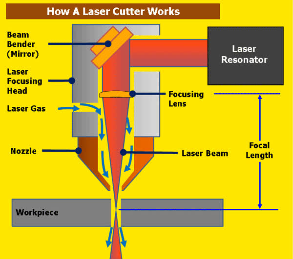
Laser cutting works by directing the output of a very high intensity light of a single wavelength. In the case of our laser cutter, the wavelength is in the infra-red part of the light spectrum so it's invisible to the human eye. The beam travels from the laser resonator where the beam is created, through the machine's beam path which is a series of mirrors before it finally hits the focusing lens, which then goes through the bore of a nozzle before immediately reaching the workpiece. This high power density is used for rapid heating, which melt or vaporise a material. The materials can range from cardboard and wood, to stainless steel or aluminium.
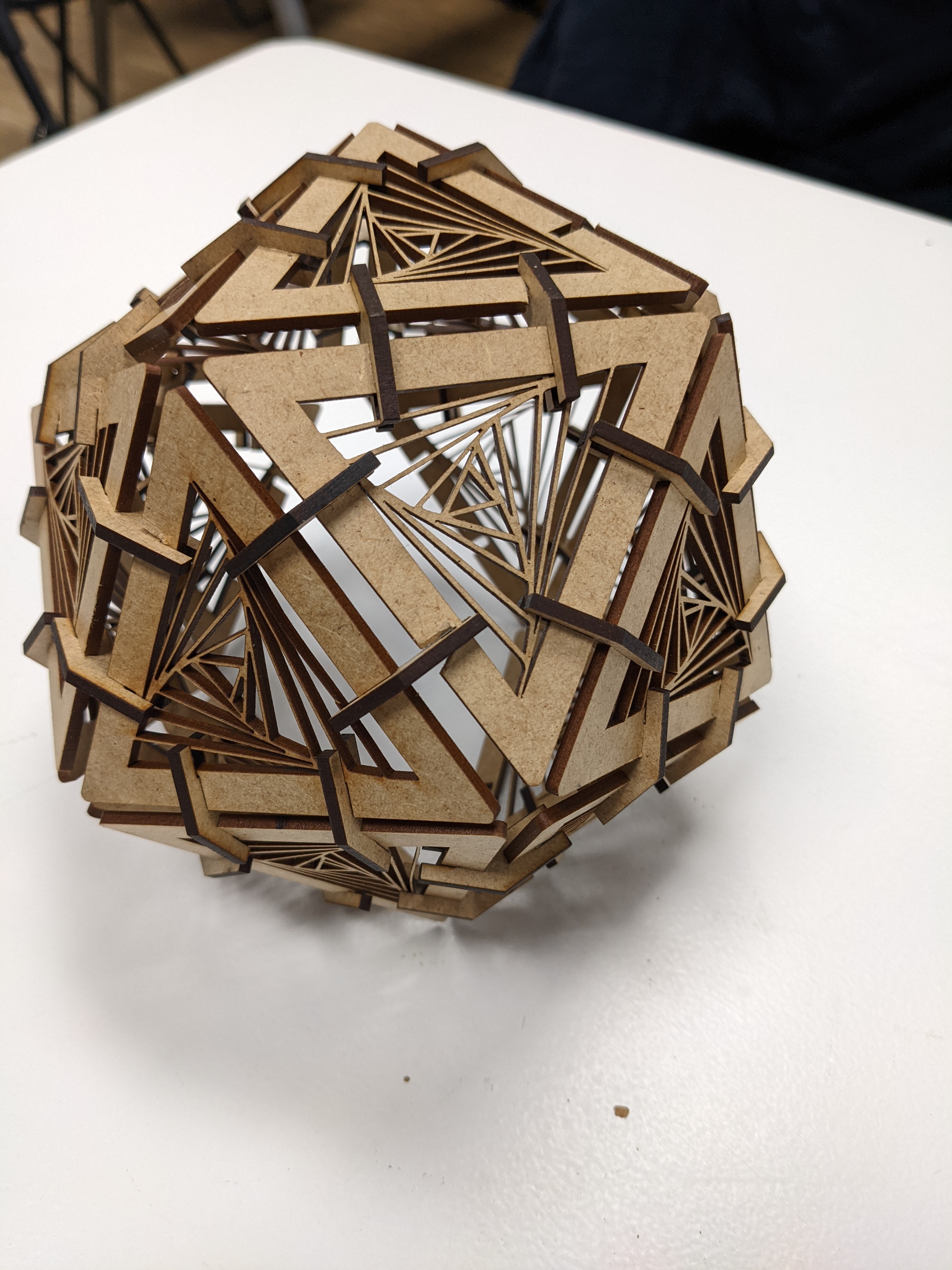
Laser Cutting: Icosahedron
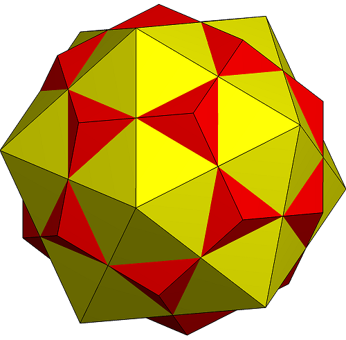
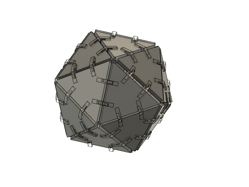
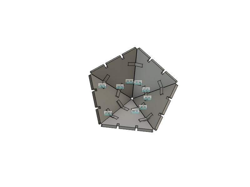
Geometry is awesome. The clean, elegant lines and corners give me so much peace. Hence why I've decided to do a convex regular icosahedron for my personal laser cutting project. An icosahedron is a 20 face polyhedron made out of equilateral triangles that fit together at certain offset angles from each other. Each triangle carries 2 slots on each side for the connector pieces, which are themselves bent in the middle so the triangles can connect at the proper offset angle. The objective of this assignment was to use parametric design to create the lines for the triangle.
Design in Fusion 360
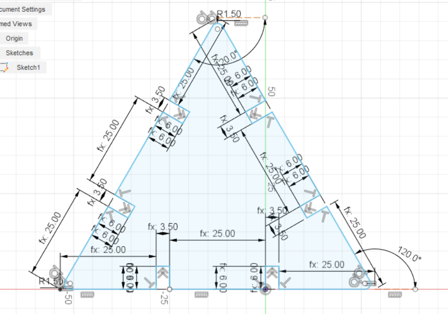
First, I made the design in Fusion 360 starting with the triangle. I decided to do a relatively small shape since I would have to cut out this triangle 20 times and I am also sharing both laser cutting machines with the rest of my classmates and the fab academy students.
I decided to use the 3mm thick MDF for the structure. Although the material thickness is 3mm, some material will be burnt away by the laser during cutting. It is important to do a material kerf test before finalizing the dimensions on the design, which allows you to understand the amount of material that gets burnt by the laser. After an initial mistake in cutting, I realised that the MDF I was using was in fact 2.3mm
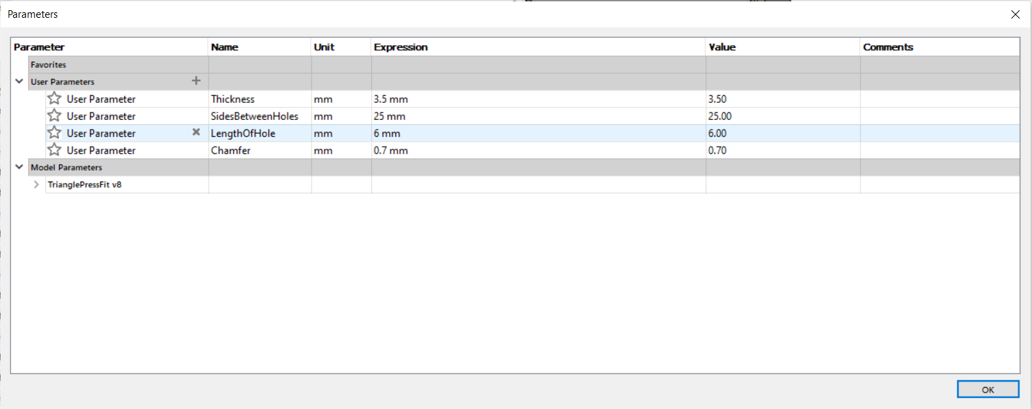
On Fusion, I inserted the measurements into user parameter. If the dimension changes, I can make the change in user parameters, which automatically applies to all measurements in the model.
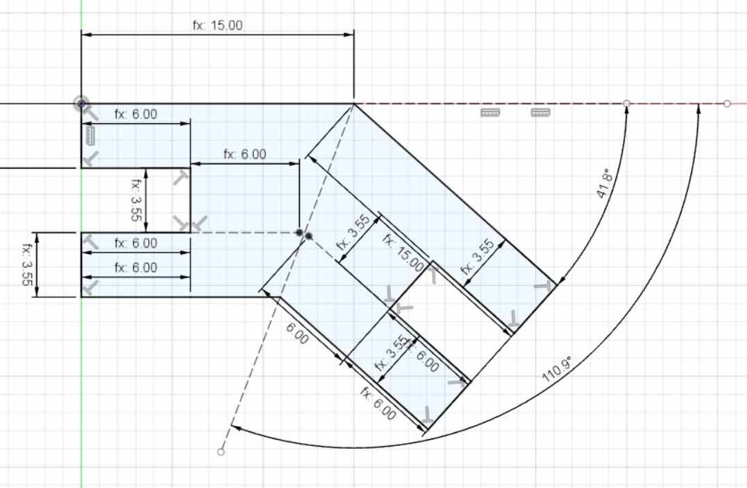
After doing the measurements and putting together the triangle, I worked on the connectors. In order for the icosahedron to work, the angles have to be correct. I got all the necessary info from wikipedia.
Once I modeled the triangles and the connectors, I joined them together using the 'joint' feature on Fusion 360 that allowed me to model how the object would fit togeter in 3D.
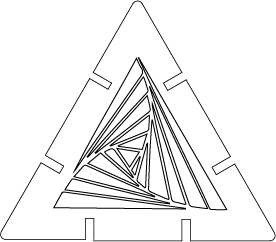
I then wanted to do a nice design on the triangle, so I transferred it to Illustrator and made a design.
To the laser!
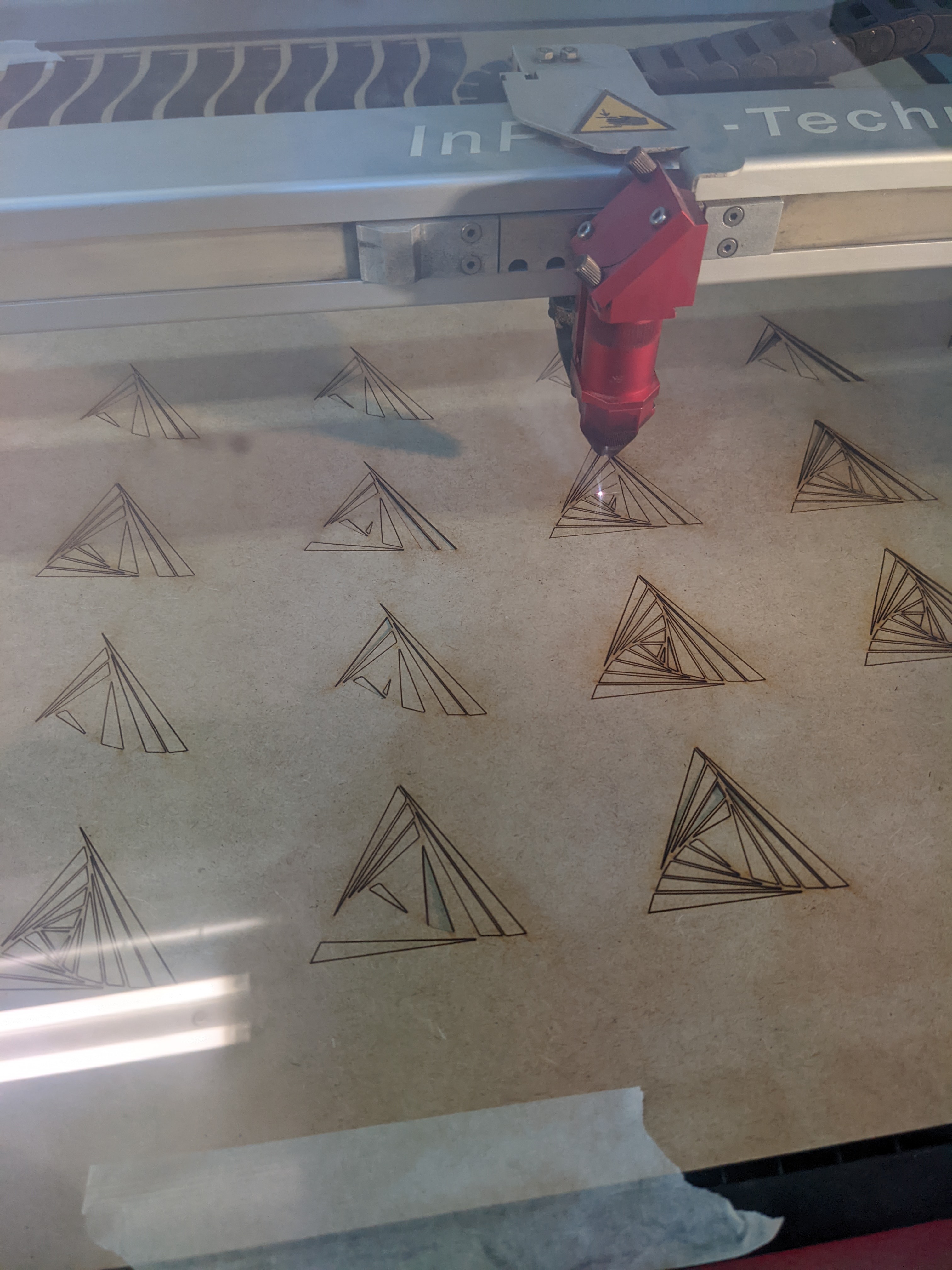
Let's get cutting! First I transferred the files to the cloud at IaaC and downloaded them on the laser cutting computer. I then opened the file on Rhino and cleared up the last few details, such as changing the colours on the outside and inside lines, deleting duplicates and any excess lines as well as flattening all the images on a 2D surface. After sending it to print, I set the power to 55 and the speed to 0.5. I made a few mistakes, the first time it was too small and the second time it was too large.
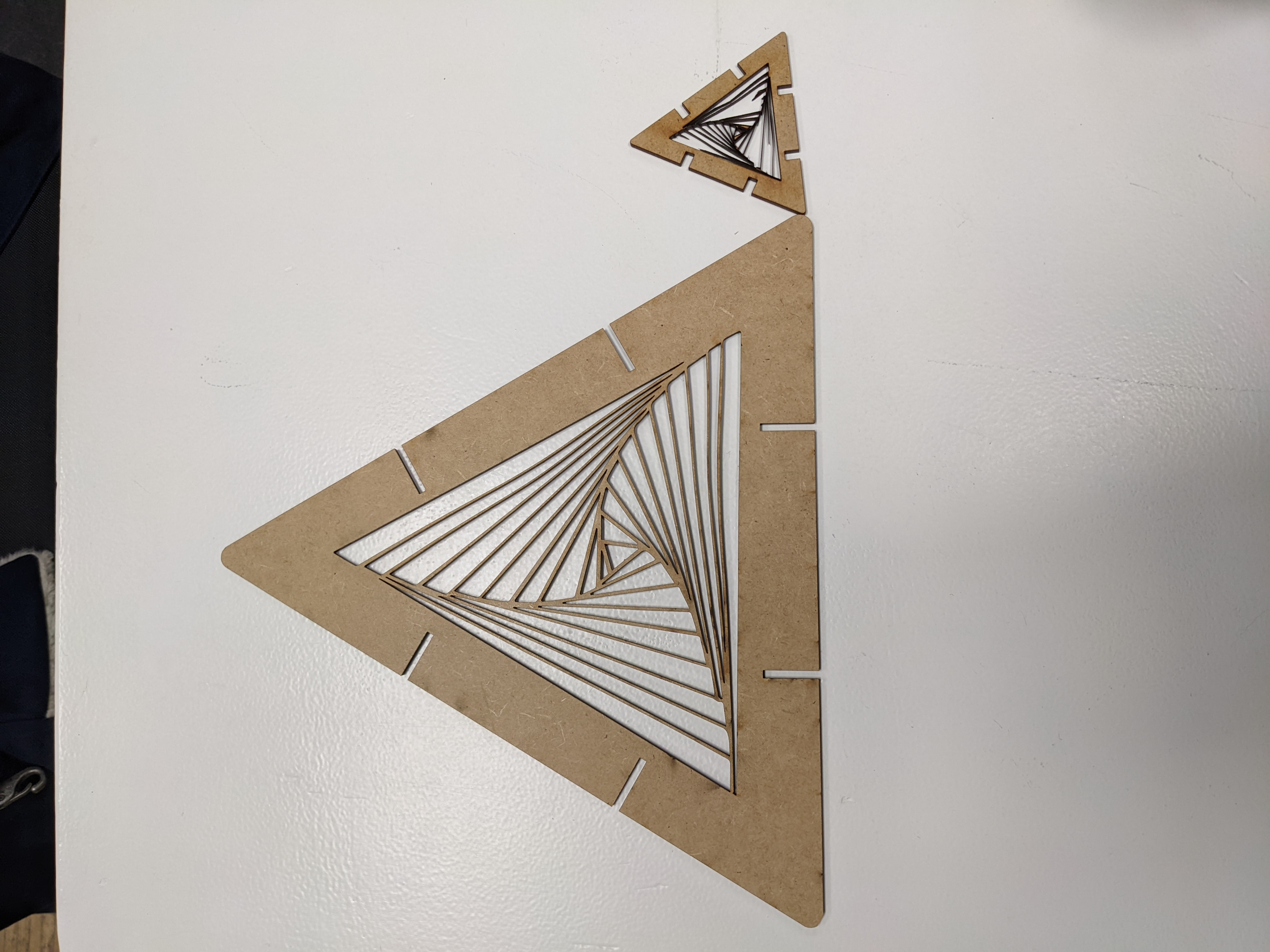
After the 3rd attempt, I finally got the thickness and the size right and could print everything in a little over 10 minutes. I then went on to assemble the whole structure. I realised the new connectors I had made were too short and so I went back to the drawing board to make them a little longer. After fixing this mistake, I could finally assemble the final Icosahedron.