Introduction
During week 6 we designed a PCB that we then had to mill it, solder it, and make it work. The design I made for week 6 was a hello world board with a 14 leg attiny44 which was very limited. For that reason I decided to make a continuation of the design we had started for micro challenge 3 which we never finished (barely made it past a breadboard) so my plan was to finish off the design and fabricate it to make it work as we intended to make it work during week 6.
The design
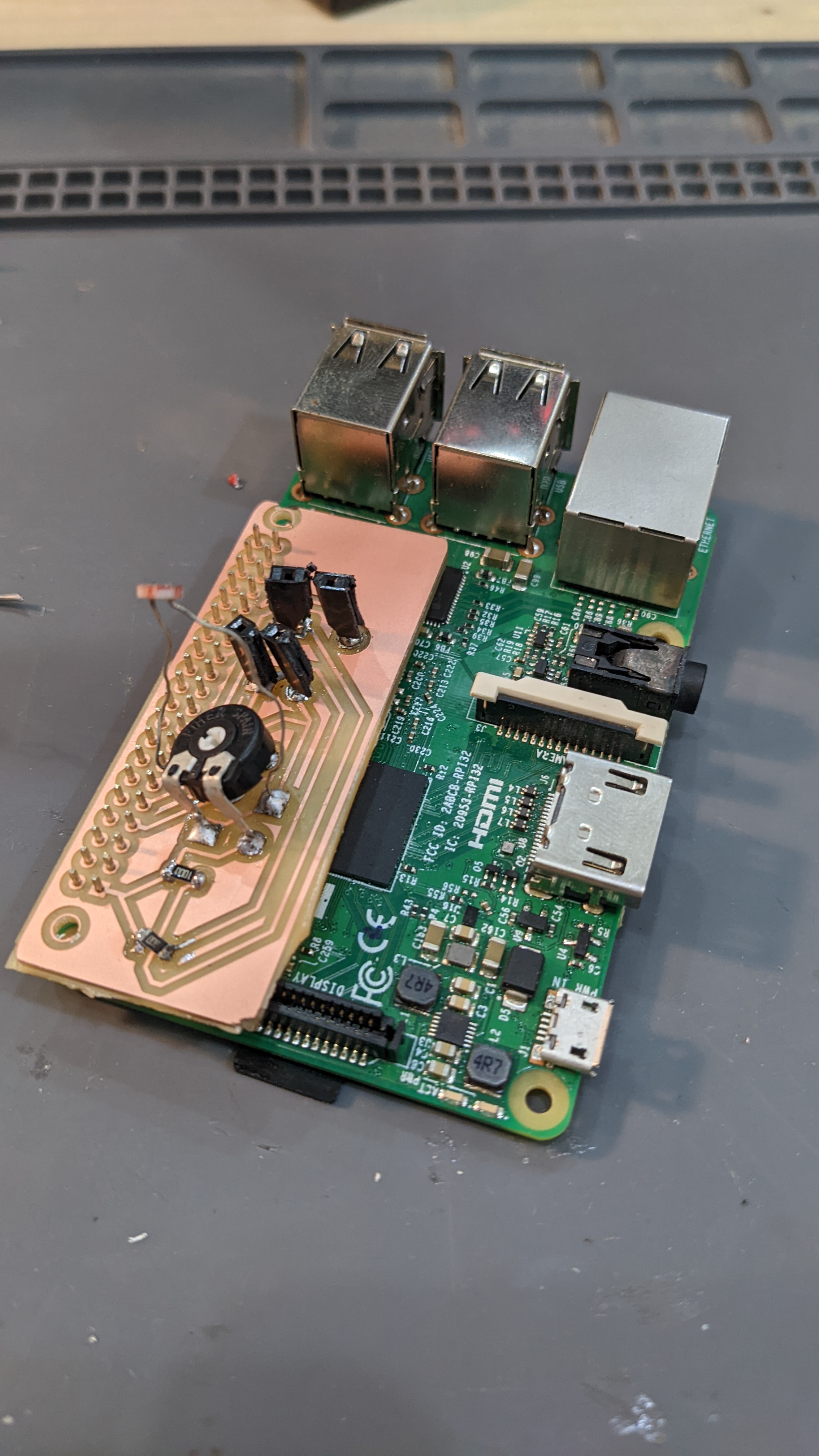
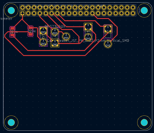
Following up on the embedded programming week, the design of this PCB aims to work as a hat for a Raspberry Pi and fulfill the functions of communicating with an input device (phototransistor, buttons) and an output device (speakers).
The design featured the following components:
- A phototransistor
- Two buttons that are held in cylindrical shaped 3d-printed holders
- A potentiometer
- Two resistors
- 24 holes to fit on the Raspberry Pi
 (I know I know I shouldn't have used the wires and instead should've used the labels)
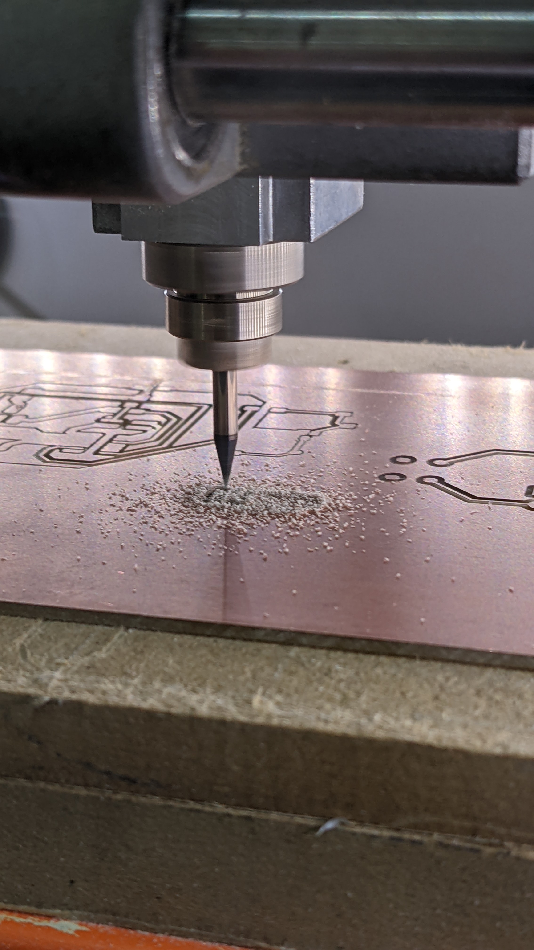
Milling
This part of the process was incredibly painful. I must've gone through like 10 PCBs before finally getting it right. I made a bunch of mistakes such as:
- The proportions were too big (PCB end up being too big for the components)
- The resolution was too low (The lines were crooked)
- The end mill broke
- The PCB would move mid-mill
- I would forget to invert the colors on the mods
- The holes were too small
- Among others
At the very least I feel like now I am an undisputed expert milling PCBs. I feel a little guilty about all the material I've wasted though, but I guess that's part of the learning process.
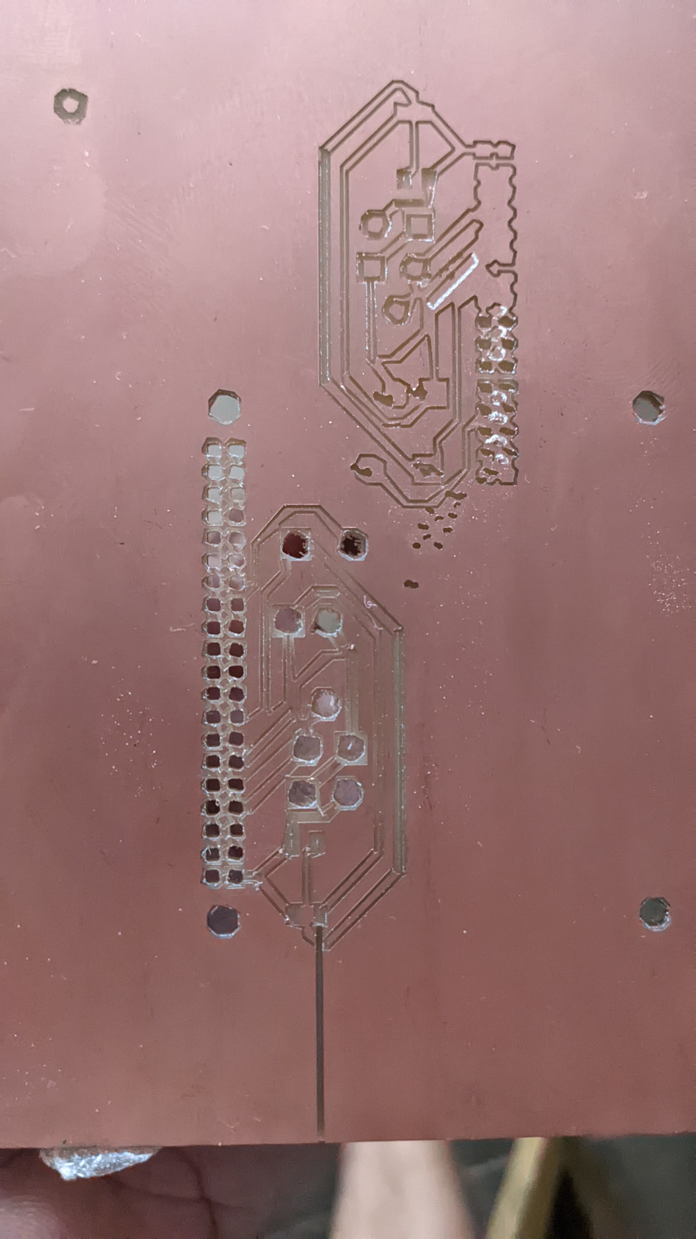
Finally after many (many) trials and mostly errors, I could mill a PCB properly.